Quick links – click to jump to contents.
What are the benefits of data filtering / data qualification?
How to set up data filtering with LOG Storm Studio?
SPI and I²C decoding with LOG Storm Studio
What are the other benefits of a ‘data logger’ over a ‘logic analyzer’?
Logic Analyzer or Data Logger? – Watch presentation
LOG Storm – General specifications
What are the benefits of data filtering / data qualification?
Logic analyzers are key tools for that process – they offer visibility over what happens in your digital electronic system.
Data filtering = Extending visibility
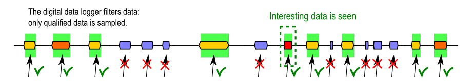
Data filtering – also called ‘Data Qualification’ is a very efficient extension for logic analyzers. They turn the device into a ‘data logger’: filtering techniques allow collecting digital information that matches user-defined properties.By exploiting an ‘a priori knowledge’ of the data to be observed, you are able to focus on the traffic that really matters and save on the resources of your logic analyzer / data logger.
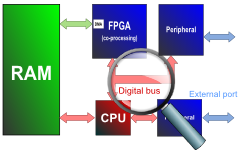
Let’s say that we are observing the data traffic that transits on a digital bus. Data originates from various sources in the system and go to various directions. For instance, each message could bear an address for a specific peripheral connected on the bus.
Let’s say that we would like to understand what caused a bug in the system – for instance a wrongly scheduled message on the bus, represented in RED on the figure below. We use a logic analyzer with a given trigger and fill-in its memory with data sampled on the bus.
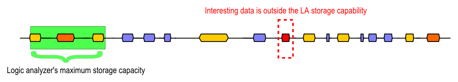
- Observation #1: the logic analyzer’s memory limits what is observable from the trigger
- Observation #2: the memory is filled with samples even when the bus is IDLE
Logic analyzers can automatically restart and re-trig a new window. Looping triggering and data captures with a logic analyzer introduces latencies between captures.
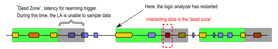
- Observation #3: even with trigger rearm, we can still miss data located in the ‘dead zones’
In the example below, the LA triggers capture only when there is traffic actually transiting on the digital bus. The blue areas are even excluded from the capture. The conditions for capturing data are managed from the instrument’s hardware, enabling a faster (cycle-accurate) ‘rearming’ of the capture condition, and eliminating dead zones. Data qualification provides a cycle-accurate control over when the logic analyzer / data logger captures digital data and when it is left IDLE.
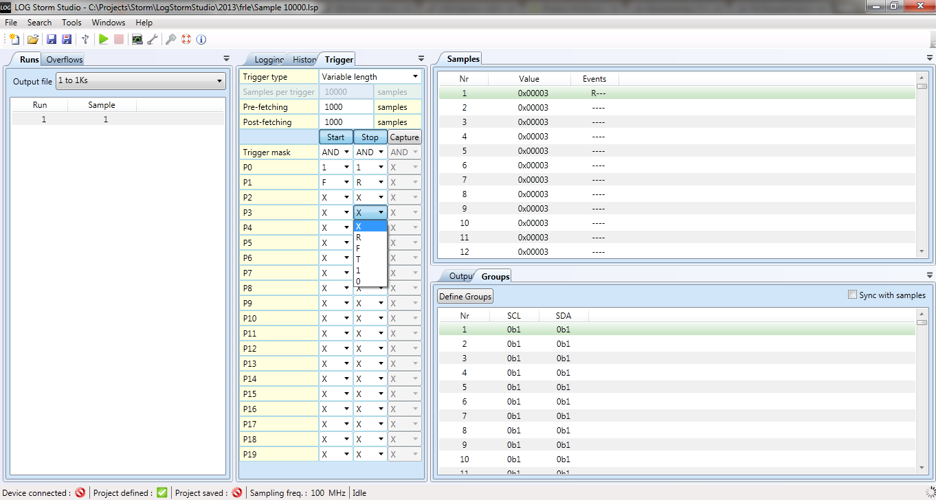
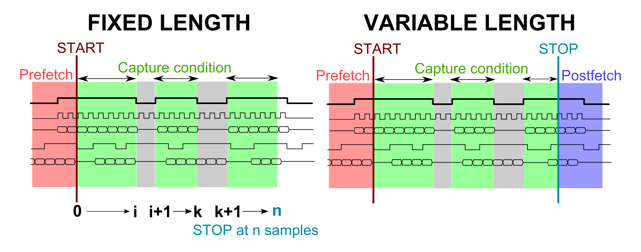
How to set up data filtering with LOG Storm Studio?
- Fixed length: it defines a START condition and a CAPTURE length. It also foresees a pre-fetch option for capturing data before the START condition.
- Variable length: it defines a START condition and a STOP condition. This type of capture includes pre-fetch and post-fetch options for capturing data before the START and after the STOP conditions.
All conditions (START, STOP, ENABLE) are defined as logic equations built on LOG Storm’s inputs.
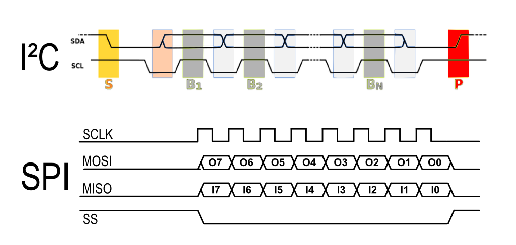
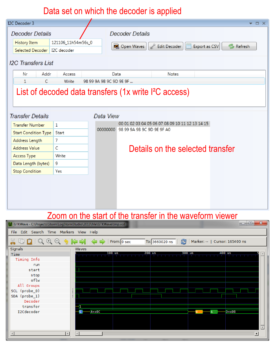
SPI and I²C decoding with LOG Storm Studio
SPI and I²C analysis can be applied to stored data sets after capture. Simply define the protocol’s signals from the 20 channels of LOG Storm and obtain a list-style, exportable decoding and visualization in the built-in waveform viewer. This way, you can actually monitor the SPI and I²C messages on the target bus.
Did you know?
You can test LOG Storm Studio’s ‘look and feel’ by yourself. See how you can apply a protocol decoder on a set of data and/or visualize raw data. Please download and install LOG Storm Studio for free, together with the example of pre-recorded data set (see .lsp file available from this site). You don’t need a license unless you want to use LOG Storm hardware.
Yes I'd like to try it! →
What are the other benefits of a ‘data logger’ over a ‘logic analyzer’?
Like a logic analyzer, LOG Storm uses an internal memory to store samples. LOG Storm uses this memory as a temporary buffer organized as a FIFO. LOG Storm regularly sends packets of data to the PC over the USB connection. This data is stored as files onto the PC hard disk.
Hence, unlike most logic analyzers, LOG Storm is able to fill-in multiple buffers of data and automatically restart sampling more data. This ‘always-on’ behaviour is this of a data monitor.
Did you know?
With a huge 8 megasample buffer, LOG Storm demonstrates more memory capacity than even 20 k$-range bench-top logic analyzers. In addition, multiple windows-data capture or always-on behaviour coupled with automatic data streaming to PC allows collecting more data over much longer periods of time.
What if the sampling rate exceeds the maximum throughput on the USB?
LOG Storm studio simply reports it has encountered an overflow condition. It resumes operations automatically once space is available again in the memory. While recovering after an overflow, LOG Storm simply discards the sampled data. Sustained throughput on the USB connection depends on the PC. If too many overflow conditions occur, you should review the capture conditions and try to lower the total bandwidth needs.
Logic Analyzer or Data Logger?
[prezi id=”http://prezi.com/p50k5_mypfpi/logic-analyzer-or-data-logger/” width=920 height=400 lock_to_path=0]LOG Storm – General specifications
| Device type | Logic Analyzer, Digital Data Logger, SPI & I²C Analyzer |
| Other names | SPI & I²C bus monitor, High-speed data logger, Bus recorder |
| Sampling frequency | 100 kHz to 100 MHz |
| Data width | 1 to 20 bit |
| Memory | 8 MS on each data bit |
| Protocol decoders | SPI, I²C on any of the 20 data lines. Parallel decoding of multiple SPI / I²C bus supported with display in waveform viewer. |
| Advanced features | Data qualification / Data filtering – hardware configurable data capture. Fixed-length or variable length trigger type. Always-on / automatic rearm logging capability. Data streaming to PC over USB, enabling gigabyte data storage. User-defined file size for storage on disk. |
| Trigger I/O resources | Trigger and capture condition built on the 20 data bits (P0…P19) |
| Clock I/O resources | 1x Clock in for state analysis – up to 125 MHz |
| Power supply & Voltages | USB-powered I/O voltage from 1.25V to 3.3V Default I/O voltage: 3.3V LVCMOS I/O voltages lower than 3.3V must be supplied externally Max 8 mA per I/O |
| PC connection | USB 2.0 high speed |
| Software | LOG Storm Studio – Win 32/64 – GUI & free C/C++ API provided Waveform viewer included |