Understand when a Logic Analyzer can really add value to your MSO.
With Mixed-Signal Oscilloscopes (MSO) being everyone’s ‘Engineering Swiss Army Knife’,
why would you need an additional Logic Analyzer?
Mixed-Signal Oscilloscopes (MSO) with sampling rates in the GHz range and 8+ digital lines can be priced well under 3.000 $.
For this reason, many in the electronic industry are announcing the demise of the logic analyzer as a piece of stand-alone equipment.
It is no surprise that Mixed-Signal Oscilloscopes are to be found in most electronic engineering labs today. They are versatile, affordable and have become the basic instrument for any engineer who is testing, debugging and verifying electronic systems. In fact this could be the only instrument that most electronic engineers will ever have to (or want to?) use for 90% of their lab time.
So, it is wise to spend part of an initial engineering or test lab budget on an MSO.
But does this mean that you will not need a logic analyzer (LA)? Read on.
Oscilloscopes vs logic analyzers – a refresher
Digital oscilloscopes and logic analyzers are based on sampling techniques. Electrical signal (usually voltage) measurements are transformed into digital value by a high-speed analog-to-digital converter (ADC) and stored into memory at regular intervals defined by the instrument’s sampling clock.
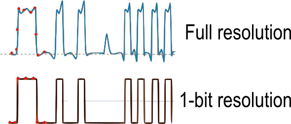
A logic analyzer can be thought of as a scope with 1 bit vertical resolution on all channels. It displays signals as logic (binary) values, according to whether the measured voltage is above or below a conventional voltage level called ‘threshold value’. That is the first fundamental difference between a oscilloscope and a logic analyzer.
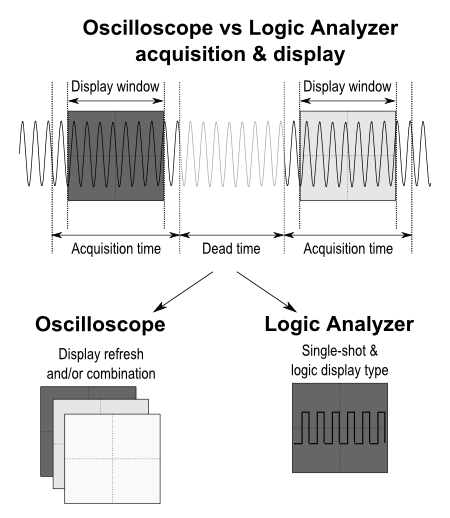
The other fundamental difference between an oscilloscope and a logic analyzer is how the sampled values are displayed. In its most common mode of operation, an oscilloscope is essentially a device that repeatedly captures a window of events of a given length (defined by its total memory) and refreshes the display of a portion of it on a screen. Many oscilloscopes simulate ‘persistence’ by superimposing multiple captured windows on the display and by modulating the screen pixel intensity.
A logic analyzer is mostly used for single-shot captures (no superimposition of successive captures) and to analyze the sequence of events of sometimes over more than 100 digital signals before and after an event called trigger.
It was the appearance of microcontroller-based systems that required the creation of tools like logic analyzers. First, there was a need to observe digital busses – and hence have more than 2 or 4 channels. Second, there was a need to see the signals the way logic circuit does, i.e. at the sampling events of the circuit, in the form of binary values. With time, logic analyzers have turned into less ‘pure’ instruments with an ability to perform some analog measurements – especially for checking threshold levels, detecting glitches and verifying the compliance of signals to specific I/O standards.
‘Real-time’, really?
It is very common to hear that the ‘real-time display’ capability is the difference between a scope and a LA. In fact, the automatic display refresh may mislead users into thinking that the user sees data ‘as it occurs’. But note that the scope display isn’t really refreshed faster than what the eye is able to see (that is about 30 times per second). In most cases, a LA is used by first capturing a bunch of data and then spending ‘some time’ to analyze it. LA’s repetitive trigger capability also enables refreshing the display based on the repetitive occurrence of a trigger event. It is true that data is displayed and presented differently in digital scopes and LAs, but fundamentally, in the two cases, the tools proceed by sampling signals and storing the samples into memory.
MSO = Oscilloscope + Logic Analyzer?
Well, mostly. A mixed-signal oscilloscope (MSO) features ‘analog channels’ (usually 2 to 4) and ‘digital channels’ (usually 8 to 16). On both types of channels, data is sampled at the MSO’s maximum sampling rate (1 GHz, typically). The sampling clock is usually generated internally by the MSO. In other words, the reference time base for sampling is not correlated with the data – this is what is called ‘Timing Analysis’. And of course, the signal vertical resolution is kept from the analog channels and is reduced to 1 bit for the digital channels.
MSOs are able to perform some of the functionality traditionally reserved to LA:
– Timing analysis on digital signals
– Ability to see more than 2 or 4 channels: on modern MSO, 16 digital inputs are available
– Digital signal integrity check. From this respect, being able to visualize both the analog extension of a digital signal and its digital version on the same screen is certainly an improvement compared to using a scope and a logic analyzer separately.
With electronic systems evolving towards more complexity, debugging involves a mix of analog and logic types of potential issues. MSO’s trigger can be defined for either type of signal. Repetitive (oscilloscope-like) or single-shot (logic analyzer-like) types of display can be used as well. It must be noted that displaying analog and digital recording on the same screen as time-correlated data is one of the biggest advantages of MSOs.
When your MSO needs help…
Let’s review some of the logic analyzer’s capabilities.
1) Logic analyzers have a larger number of digital channels than MSOs
Traditional bench-top logic analyzers can count up to 128 digital channels or more. On MSOs, there are usually a maximum of 16 channels. ASIC and FPGA design engineers – ‘heavy LA users’, often need 32 to 64 signals and more to decode bus transactions or visualize the internals of a FPGA.
But for 80%-90% of the time, however, and even if you are in IC design, 16 digital channels are plenty.
The rare 1%-10% cases where you’d like to see 100 digital signals in parallel may not justify the investment in a high-end 100 channels logic analyzer (price range: over $20,000).
FPGA (Field Programmable Gate Array) design is an area where large channel-count logic analyzers used to be the basic equipment for debugging. Adding a connector on board and observing the chip through its I/Os – or even putting a debug connector on chip-to-chip interconnections was very useful for troubleshooting the design. In addition, thanks to its programmable nature, FPGAs allowed many internal nodes to be monitored by simply ‘routing’ them onto the I/Os connected to the LA.
Things have changed. FPGAs are getting so advanced that observing chip behavior through external digital I/Os may not make much sense any more, even if you see 100 of them in parallel. Nowadays, an FPGA may run at over 300 MHz internally- and putting a 100 pin high-speed parallel connector on a board brings excessive board constraints (noise, number of layers, crosstalk, etc.). In addition, the chip I/O buffers sometimes are unable to run at the same speed as the internals of the chip. Other types of approaches – such as using ’embedded logic analyzers’ or software-based types of debugging have become far more efficient and cost effective.
The ‘number of digital channels advantage’ of logic analyzers vs MSOs must be considered cautiously. 16 to 32 digital lines will be enough for most of the engineers. Logic analyzers with 68 to 100 or even more channels can make a difference where there is an absolute need to see more digital signals in parallel. However, this must be carefully balanced with the constraints of adding the required debug connector to a system. In a context where the digital complexity shifts towards ‘inside the chips’, it is increasingly difficult to probe high frequency signal without creating signal/data integrity issues. For this reason, the investment (> $20,000) in a logic analyzer with a large channel count must be carefully weighted.
2) Logic analyzers have a larger memory than MSOs
While there may be exceptions to this statement (since MSO equipment is constantly evolving) this is one of the potential strength of a logic analyzer to justify its addition to a MSO: it helps seeing a larger ‘window of time’ before and/or after a triggering event. Seeing a larger time of execution of your digital system is of great value during debug. It has the potential to speed up an understanding of why a bug occurs and hence, speed up bug correction. It can pay for itself rather quickly!
A large total available memory size in a logic analyzer adds a significant value in addition to an MSO. Large memory means seeing more of the history of observed signals.
3) Logic analyzers allow more complex triggering or data filtering than MSO
The total amount of available memory is not the only parameter to consider. How the instrument uses the memory to store data is equally important. What you need to know is how much of the history of the signals you’ll be able to observe and how useful this information will be to debug your system. Let’s examine how logic analyzers and MSOs are able to select data.
Most MSOs are able to trigger on simple events – a voltage level or a digital value or transition on specific digital lines. Where they also provide simple serial bus decoding such as I²C or SPI, MSOs are also useful for utilizing serial triggers – that is, stopping the capture on the occurrence of a predefined serial value on a digital line.
On the other hand, all logic analyzers are able to trigger on a ‘parallel value’. They are also able to build up complex sequences of conditions to ultimately trigger the capture of data.
As a matter of fact, lots of digital system busses are ‘quiet’ most of the time. Excessively basic logic analyzers – even when they are full-loaded with memory – risk of wasting memory resources with samples even if nothing happens. To make the most of the logic analyzer memory, several strategies coexist.
Some logic analyzers only store the data transitions, thereby potentially compressing the collected data. This is a somewhat ‘uncontrolled’ way to save on memory and is highly dependent on the data itself.
Another strategy consists in using logic equations on the recorded data to define conditions when the logic analyzer must store the data and when it can discard it.
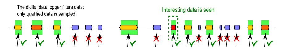
Data qualification – or data filtering – is the ability of the logic analyzer to record only the data that matches user-defined criteria. In this case, the logic analyzer is also referred to as ‘digital data logger’. This strategy is based on a priori knowledge of the debugged digital system. It can be as simple as detecting a signal level (e.g. an output enable) and recording the values of a bus when this level is seen. Or it can be very more complex, like a filtering when a Boolean equation from certain digital lines is true, or even recording a predefined data quantity each time a trigger condition is encountered.
Total available memory is important but efficient data storage, data qualification and rich triggering options bring significant value to different logic analyzer products. Seeing relevant data is more important than seeing all the data. A logic analyzer capable of data qualification or data filtering (sometimes referred to as ‘data logger’) is an excellent companion tool to your MSO.
4) Logic analyzers allow looking at the signals the way hardware does.
Unlike most MSOs, logic analyzers are able to use the reference sampling clock signal of the system under test. This means looking at the sampled signals in sync with ‘the eyes of your hardware’. This mode is called ‘state analysis’, as opposed to ‘timing analysis’, where the sampling clock is generated by the equipment itself.
Running equipment in state analysis mode can be a challenge, because a clean reference clock signal from your system under test may not always be available.
Nevertheless, state analysis will provide a close insight of a system’s embedded software, allowing focus to be placed on the information seen by the hardware and speed up debugging.
Conclusions
Mixed-signal oscilloscopes are extremely well-suited to most basic and advanced testing and debugging tasks on all kinds of electronic systems. For this reason, the investment in an additional external logic analyzer must be thought out carefully.
Picking a logic analyzer just because it has 100 channels won’t probably be worthwhile, since alternative and more cost-effective debugging strategies exist.
But a Logic Analyzer with…
- a multi-megasample memory
- state analysis capability
- and data qualification capability