Quick links – click to jump to contents.
Standard or custom protocol?
How to use a standard protocol?
How to define a custom protocol?
Building up sequences with SPI Storm Studio
Running program & retrieving data with SPI Storm Studio
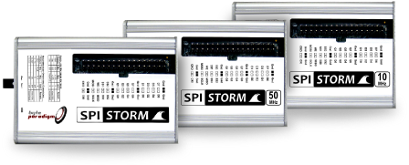
What is a SPI interface adapter and why use it? Watch presentation
SPI Storm & SPI Storm Studio General specifications
Setting up serial protocol with SPI Storm Studio
This is the primary step for using SPI Storm device. It consists in describing how you would like to access your serial device: whether you would like to write to your device, read from it or do both simultaneously. Which serial protocol would you like to to use? What are the specifics of it?
Defining MACROS
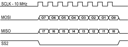
‘Macros’ are formatted commands that you can call independently to access your device under tests. For instance one given macro is a 8-bit long SPI access with SCLK running at 10 MHz and where SS2 is used as active-low signal. Another macro could be composed of a single SPI access immediately followed with a Quad-SPI write command (see illustrations below).
Standard or custom protocol?
As unique feature, SPI Storm Studio allows using standard, built-in serial protocols or defining custom protocols.
‘Standard protocols’ are pre-configured protocols delivered with SPI Storm Studio:
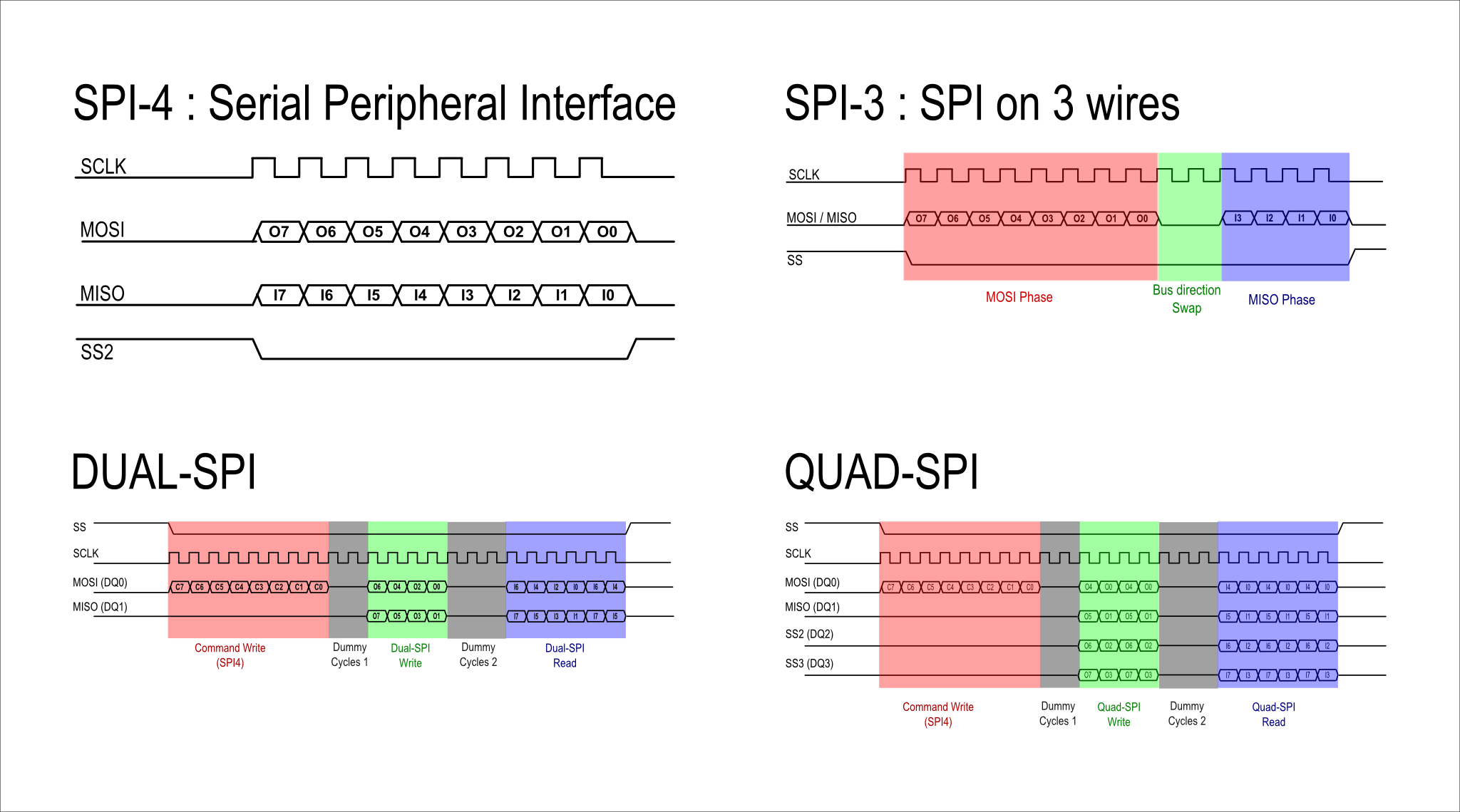
- SPI (Serial Peripheral Interface): 4 wires protocols using MOSI, MISO, SCLK and SS.
- SPI-3 : variant of the SPI protocol where MOSI and MISO are merged as a single bi-directional data line, with bus turn-around phases.
- Dual-SPI : variant of the SPI protocol that includes modes in which 2 data lines are used for conveying data.
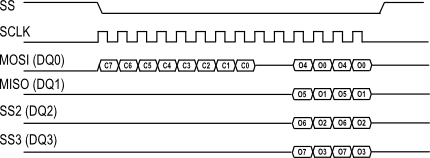
- Quad-SPI : variant of the SPI protocol that includes modes in which 4 data lines are used for conveying data.
Parameters like read / write bit length, signal polarities, clock frequency and characteristics can be specified.
SPI Storm Studio’s Custom Protocol Definition Engine is delivered with ALL SPI Storm device versions. Using this engine helps covering more access cases:
- Communication protocols that slightly differ from SPI. Specific SPI slaves sometimes require a delay between the assertion of SS and the start of the clock.
- Complex write and read commands that only use 1 data line for read and write. In such a case, the master must be able to manage sequences of commands with bus direction change
- Quad-SPI-like protocols that use up to 4 data lines to reach higher total throughput.
- Clock tick count-based protocols: some protocols require a very tight control of the clock with deterministic timings between the accesses
- Protocols with open-drain I/Os
How to use a standard protocol?
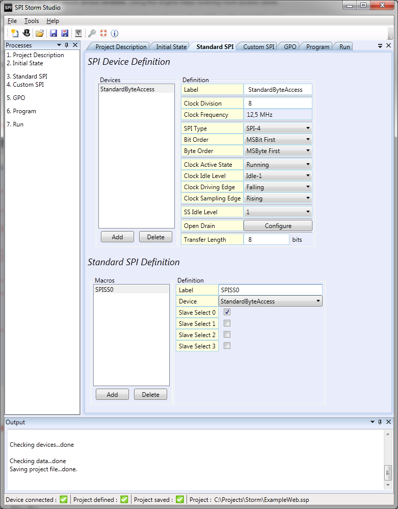
Standard protocols are pre-formatted protocols available from SPI Storm Studio.
Each standard protocol defines a ‘canvas’ for write and read accesses: when the device will write and/or sample it, the physical data lines used for the protocol, when the clock is IDLE or active, and so on.
SPI Storm Studio proposes 4 ‘standard protocols’: SPI-4 (standard SPI), SPI-3 (standard SPI with a signal bi-directional data line), Dual-SPI and Quad-SPI protocols.
A limited number of parameters must be defined for using each protocol. They are shown on the figure to the left.
Did you know?
You can see for yourself how protocols are defined with SPI Storm Studio. Simply download and install SPI Storm Studio for free: you just need a license when you actually want to use SPI Storm hardware.
Yes I'd like to try it! →
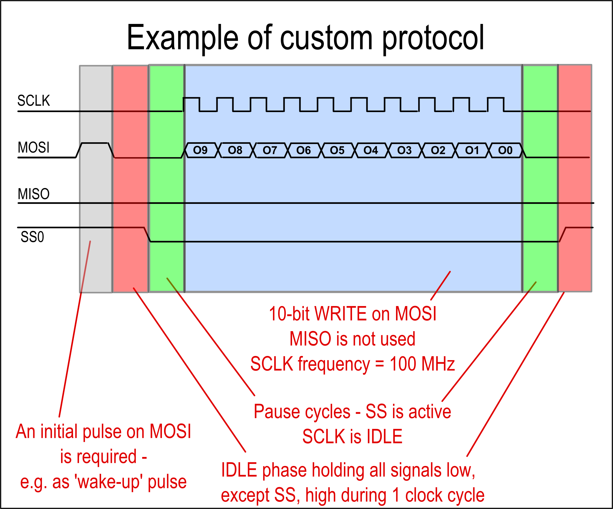
How to define a custom protocol?
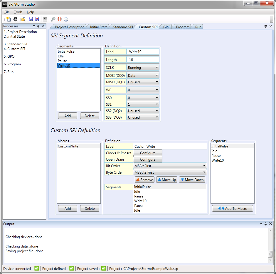
SPI Storm Studio’s unique protocol definition engine lets you define your own write and read commands.
Each protocol can be defined as a sequence of ‘segments’ with specific properties:
- Whether the clock signal is running or held at a constant level;
- The usage of each data line: output, input, unused; constant or variable;
- The length of each segment,…
Segments are the ‘building bricks’ for defining the commands (macros) used to communicate with your slave.
SPI Storm Studio software allows assembling the segments as sequences, so you are able to:
- Re-use protocols segments within the same macro or in multiple macros;
- Define protocol with a clock period resolution (up to 10 ns resolution);
- Implement complex command involving data generation and sampling;
- Carefully control how you communicate with your embedded system, or digital IC.
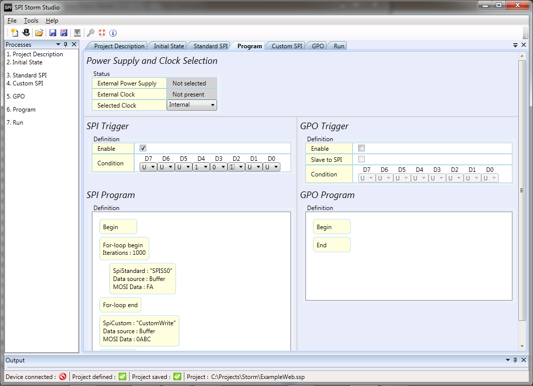
Building up sequences with SPI Storm Studio
Once you have defined your collection of commands (macros), you need to call them. You can build sequences of macros with the SPI Storm Studio built-in graphical ‘Program’ builder or use the provided C/C++ API.
From the C/C++ API, you can run a program defined with the GUI or call each macro that you saved in your project file (.ssp). Each macro is defined with pointers to data structures, allowing direct output / input data processing without having to save to a file first (please refer to documentation for more info).
Did you know?
In addition to the serial interface, you have a 8-bit GPO (General-purpose output) to generate arbitrary digital patterns. GPO patterns can be synchronized with the serial interface. Digital patterns are defined as segments and macros. They can be sourced from an external file or entered in the GUI directly.
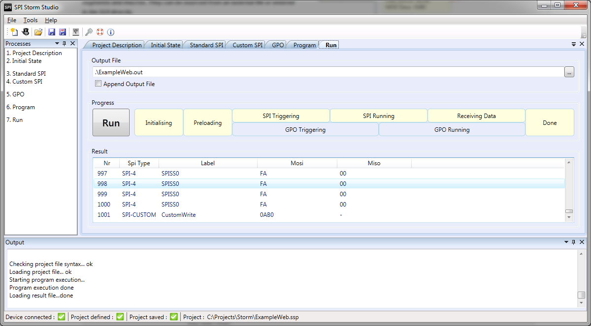
Running program & Retrieving data with SPI Storm Studio
Sampled information is collected by the device and transmitted over to your software environment (C/C++ through the API or GUI) and stored into output files.
Did you know?
The program executed by SPI Storm is compiled on the PC and buffered into SPI Storm’s memory. Unless you change global parameters such as clock frequency and phase or I/O characteristics, there will be no latency between your accesses. In other words, if your slave requires a recovery time between accesses, you need to include it in the protocol that you define.
What is a SPI interface adapter and why use it?
[prezi id=”http://prezi.com/rxgabfmknimq/what-is-a-spi-interface-adapter-and-why-use-it/” width=920 height=400 lock_to_path=0]SPI Storm / SPI Storm Studio – General specifications
| Device type | Serial protocol host adapter with USB 2.0 high speed PC interface |
| Other names | SPI Host Adapter – SPI Master – Serial Protocol Master |
| Supported standard protocols | SPI (Serial Peripheral Interface, SPI-4), Dual-SPI, Quad-SPI (SQI), SPI on 3 wires (SPI-3) |
| Other protocols | User-definable protocol, up to 4 data lines in parallel, including protocols with bi-directional signals. Flexible clock generation options – interrupted clock (hole clock) and selectable clock idle level |
| Serial I/O resources | 1x Serial clock (SCLK) MOSI (out) / DQ0* MISO (in) / DQ1* SS0 (out) SS1 (out) SS2 (out) / DQ2* SS3 (out) / DQ3* WE (out) *(in / out / bidir) – DQ# I/O direction depends on the chosen protocol. |
| GPO I/O resources | 8 general-purpose output lines (GPO) with cycle-accurate digital pattern generation (out). GPO port can be synchronized with the serial port operation.0 |
| Trigger I/O resources | 8 general-purpose output lines (GPO) with cycle-accurate digital pattern generation (out). GPO port can be synchronized with the serial port operation. |
| Clock I/O resources | 1x CKI (clock in) |
| I/O frequency range | 100 kHz to 100 MHz on internal clock |
| Memory | 32 MB total memory for in/out transfers. Split into: 10 MB for serial out, 10 MB for serial in and 10 MB for GPO*. *Memory is used for in/out data and controls. Each macro reserves some memory overhead that depends of its complexity. |
| Power supply & Voltages | USB-powered I/O voltage from 1.25V to 3.3V Default I/O voltage: 3.3V LVCMOS I/O voltages lower than 3.3V must be supplied externally Max 8 mA per I/O |
| PC connection | USB 2.0 high speed |
| Software | SPI Storm Studio – Win 32/64 – GUI & free C/C++ API provided |